There are no products listed under this category.
Shop by Category
Buzz Coils Rx
Buzz Coils: What to do if your coil decides to buzz off and the Buzz stops here.
Ford, Jefferson, Pontiac, Kingston, Detroit and other buzzy boxes that made sparks (or were supposed to) back in the day.
Buzz coils were used extensively on small engines for ignition of days gone by and by Henry Ford on the famous model T and Fordson tractor. They employed a battery and a timer switch to fire the spark plug when the switch is closed. They unlike most ignition systems produce a stream of sparks as long as the timer switch is closed and the circuit is complete. Most battery /coil and magneto ignition systems produce a single spark when the points open. The Model T Ford used a buzz coil on each cylinder and a low tension timer to energize the buzz coils in some sequence hopefully resembling the firing order within a few degrees. Here is some information to help get the spark back if your buzz coil decides to buzz off.
They employ a set of primary and secondary windings in a step up configuration like a magneto or other ignition coil. The necessary changing field in the iron core is produced by passing current through the primary windings from a battery through a set of contacts on top of the iron core. When power is applied, current flows through the primary windings creating magnetic force on the top of the iron core that pulls the contacts apart interrupting the current flow causing the magnetic field in the iron core to collapse inducing a high voltage in the secondary windings. When the magnetic field is off, the contacts come back together completing the circuit and the process repeats at a rapid rate causing the familiar buzzing. A condenser (capacitor for electrical engineering majors) is connected across the contact points to reduce sparking and intensify the spark. A capacitor is essentially two conductive metal plates separated by an insulator that charges when the points open and quenches the spark that would otherwise appear across the points raising sparking, pitting and a weak spark at the plug.
Condensers (capacitors for electrical engineering types) of old were insulated with paper and wax that tended to absorb moisture over time. The accumulation of moisture causes a slow drain across the capacitor(Electrical leakage) like a resistor connected across it. A capacitor with leakage will not fully charge or hold a charge. This resistance will also load the ignition circuit further reducing output and cause excessive sparking and pitting at the points. In many cases the capacitor can act like a dead short as if the leads were connected directly together and no spark at all.
Here we have the ever annoying buzz coil used by Henry Ford in the famous Model T and Fordson tractor. The coils themselves seemed to hold up fairly well after nearly a century. The contacts and condensers definitely not the case. Back in the day condensers were insulated with paper and wax which over time will accumulate moisture, especially here in the soggy Northwest. This causes electrical leakage as if a resistor was connected across the device. it will never fully charge or hold its charge. This will cause a weak spark at the plug and excessive sparking at the points. this is by far the most common cause of condenser failure and should be step one in diagnosis.
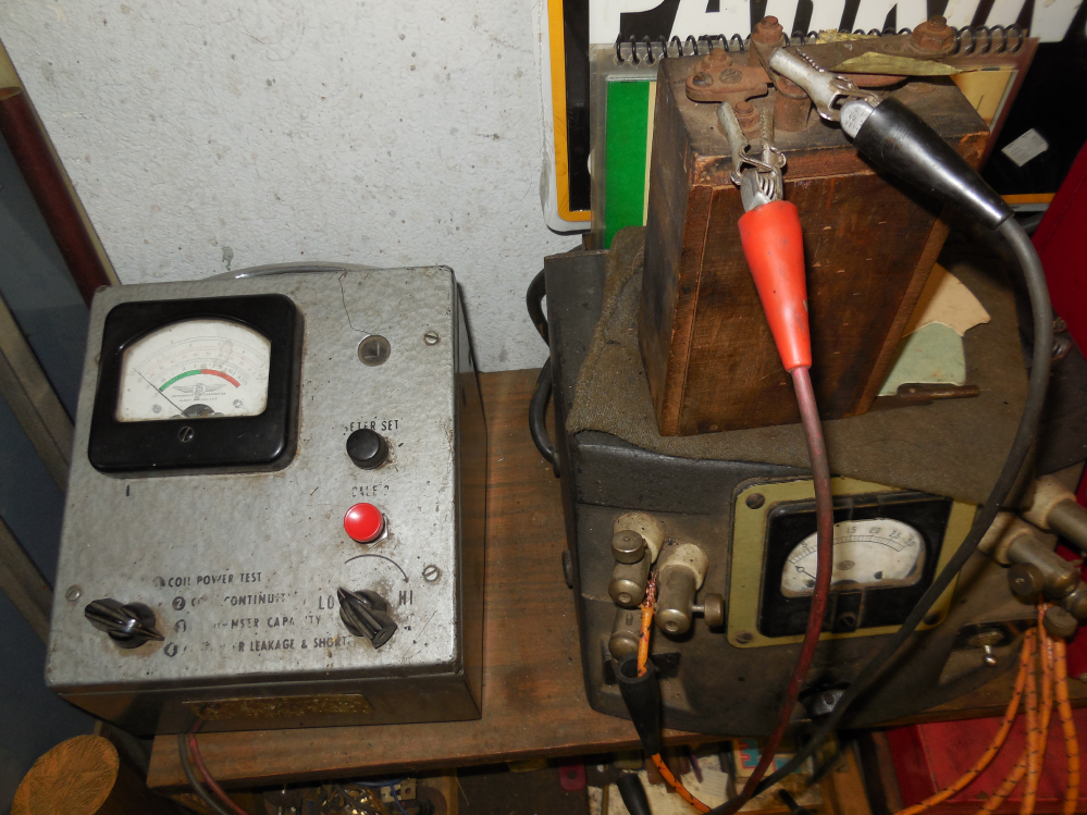
Here we are testing the condenser in a Model T Ford coil. Recall the condenser is connected across the points so we need to slip a piece of paper between the contacts (Look to the right of the black alligator clip). The very well used condenser tester is testing for leakage which is the most common cause of condenser failure.
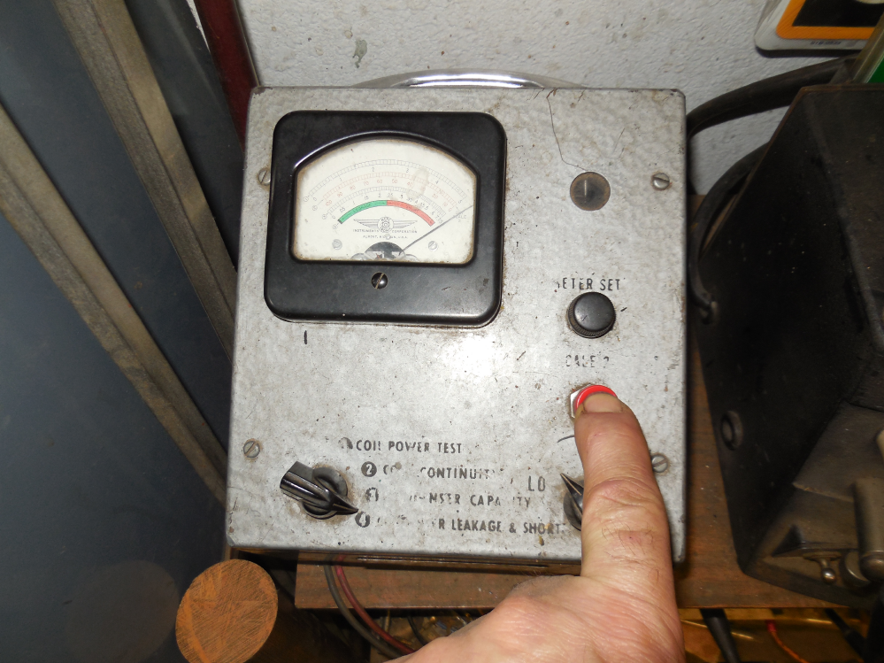
The green scale on the left denotes an acceptable amount of leakage. No leakage is best. The red scale shows excessive leakage and to the far right is a short in this case. If you don't have an automotive condenser tester as shown you can use an analog ohm meter with an R x 10,000 ohms range. Set the meter to the R X 10,000 ohms range and zero the shorted leads and connect across the points with a piece of paper between them as shown. If the condenser is good the pointer will deflect briefly to the right then back to the rest point. If there is leakage the pointer will not fully return to the rest point.
Bad condenser? We have the cure. Nearly all original condensers will be bad. The Rx is to remove the old condenser(A condenser is a capacitor) and replace it with a modern capacitor of equivalent capacitance that is designed for spikes of current that will appear when the contacts break.
The first step is to get inside the wood box.
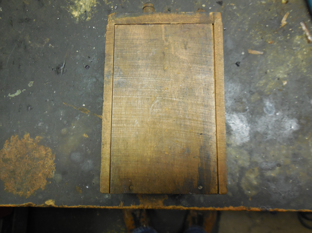
Here we see two small nails or sometimes a single staple. Pull them out with a small pair of side cutters and slide the wooden cover off.
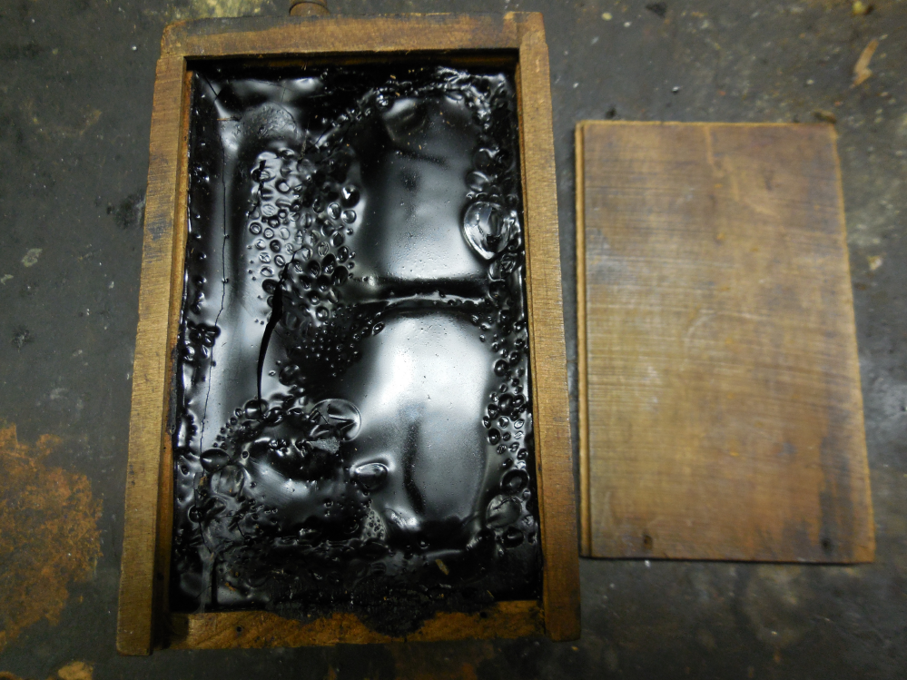
On the right we see two banks of windings that form the high tension output buried in black sticky goo. Stay clear of them as they are fragile. The offending condenser is on the far left against the side cover.

With some careful scraping we can see the top edge of the condenser on the left. It is shaped like a small bolt of cloth. There will be a lead wire down the top of the coil and the bottom that connect to it.
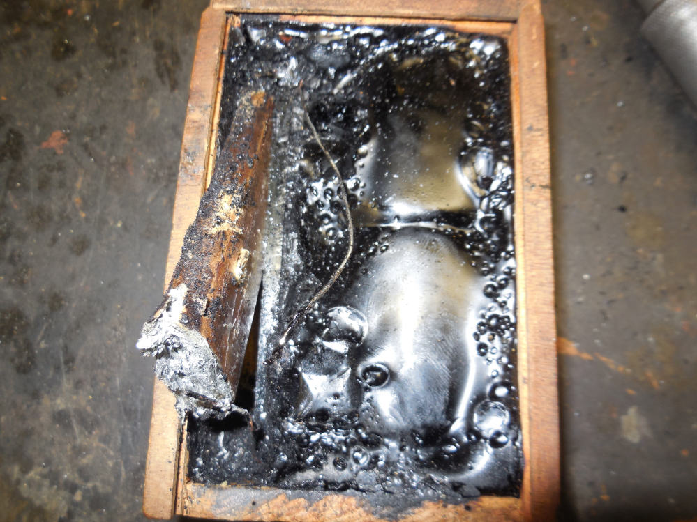
The next step is to remove the offending condenser. Find the short wires at the bottom and pull them out of the end of the old condenser. Next pry the end of the device upward with a screwdriver or corkscrew. One can also thread a wallboard screw into it and pull it out. The leadwire at the top of the condenser should be secured and/or insulated so it cannot touch the other bare lead wire.

The final step is to install the capacitor. Most Model T Ford parts dealers have them or can order from TubesNMore AKA Antique Electronic Supply in Tempe, Az. These are the famous "Orange Drop" capacitors. They are a high performance device designed for spike currents that will appear when the points break. The capacitance is from .4-.5 Microfarads rated at 400 Volts DC. These are robust and work very well. One lead goes to the upper wire and the other to the lower. These are light years ahead of the stock devices. Solder them in place, replace the cover and set the coil up as usual and all will be well. Once the coil has a new modern capacitor the next step is to adjust the clearance and tension on the spring that will affect the current at which the coil will begin to buzz. The Model T and Fordson employ a flywheel alternator whose output us an AC sine wave. it is important that all coils fire at the same point on the sine wave for even firing. To be discussed later.
Problem areas for buzz coils are like many other ignition components. The first to address with a no go and known good condenser is the contact points. Over time they can become pitted and corroded and need to be dressed smooth and set to the proper clearance and tension. The tension determines the amount of primary current to pull them apart. Insufficient tension may cause insufficient primary current to make a spark. Excessive tension will cause battery drain and premature points wear. A bad condenser will cause a weak spark and excessive sparking at the points.

This has nothing to do with vintage ignition systems but Joyce Coil and a famous astronaut Buzz Aldrin are found when you google "buzz coil"
The Jeffersons and other Buzz coils of the era.
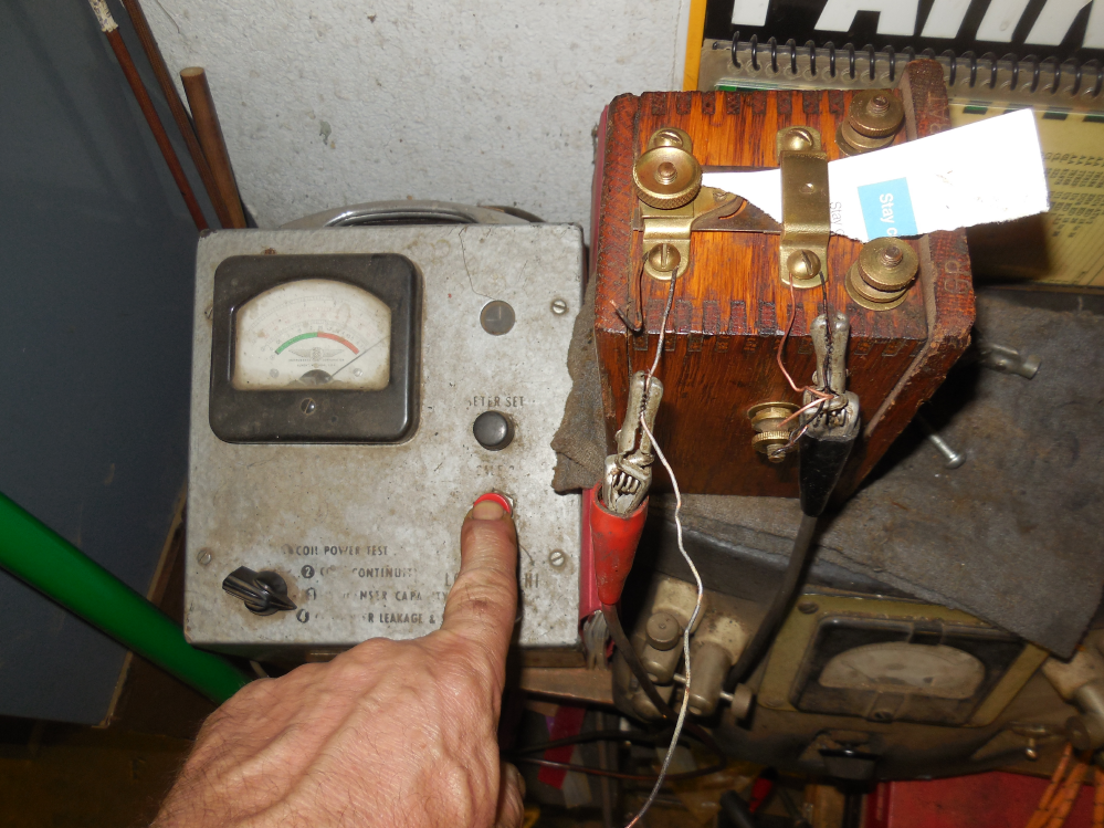
Just like the Ford buzz boxes the first step is to check the condenser(capacitor for electrical engineers) for electrical leakage with an automotive condenser tester as shown. A crude but effective way to make contact with the condenser. The condenser is connected across the points so we slip a piece of paper between the contacts to test the condenser. This condenser has severe leakage and likely a dead shorted condenser. Other buzz coil condensers are tested the same way as a rule.
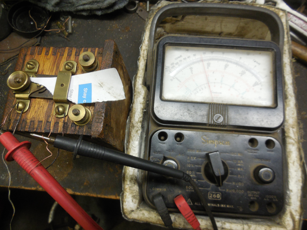
If you don't have an automotive condenser tester handy you can use an analog multimeter like the Simpson 260 in the R X 10,000 ohms range. If all is well, the pointer will briefly deflect to the right and return to the rest point on the left. If there is leakage present as shown, the pointer will not return to the rest point on the left.
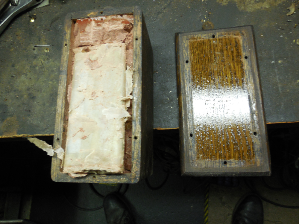
Most coil boxes have a base or cover retained by screws. Removing the screws and cover usually gets access to the condenser. It is a large device that resembles a bolt of cloth. It is hard to miss and usually in the very top and easy to remove. be mindful if the two lead wires when removing. The new capacitor will connect to them. If the condenser is not readily apparent it may be on the other side of the box. Best to avoid too much digging and probing as you can damage the fragile high tension windings and ruin the coil.

This Lemke-Briggs condenser is almost a dead short but easy to retrofit.
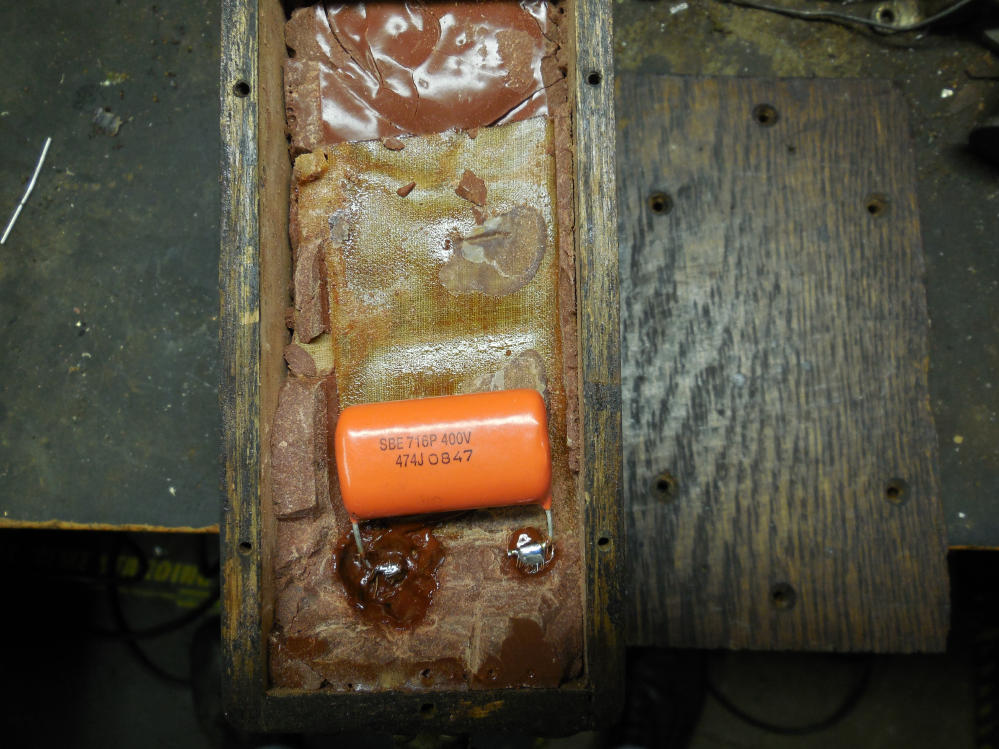
Here again the condenser is replaced with a modern capacitor. Nearly all are rated at .4 -.5 Microfarad at 400 volts DC. Order from a Model T Ford parts jobber or TubesNMore AKA Antique Electronic Supply. reassemble the lid, polish the points and adjust so the coil will buzz with 6 volts connected. Best to test buzz coils with a 6 volt battery and not a battery charger. The spikes created by the coil will destroy the diodes in the battery charger. Don'y ask me how I know that!!! Also always have a path or short gap to ground for the high voltage(plug lead) or the high voltage will find its own path to ground in the form of a carbon track and ruin the coil.

This is a later Jefferson model 51 coil. Most coils have the offending condenser under the wood cover retained wuth screws. The Jefferson 51's did not. That would make too much sense. The earlier model 51's had a round brass emblem.

The Jefferson model 51 coil box has a cover retained with screws like most coil boxes of the day but when the cover is removed the condenser is not there.
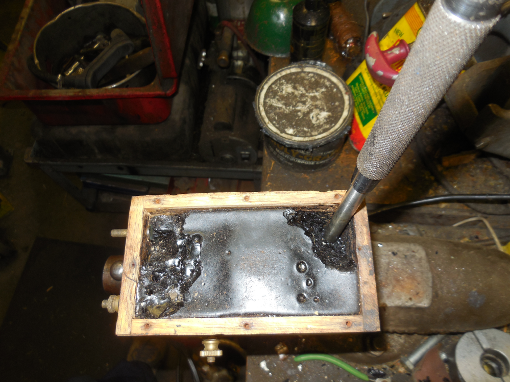
The wisdom in this case is to not dig for the condenser in the black goo. If you are looking at the side where it resides it will be obvious. Digging into the black goo will likely dig into the fragile high tension windings and it is rewind time. Time consuming and expensive. Best to avoid. For come odd reason Mr Jefferson put the condenser in place on the other side of the box under the glued on cover. To get into the box we need to remove the glued on cover. To gain entry the best way is to drill a 3/8" hole in the lower right hand corner deep enough to get through the goo but not penetrate the glued on wood cover. Next use a punch the size of the hole to remove the glued on cover. A few good raps will get it off with minimal or no damage.
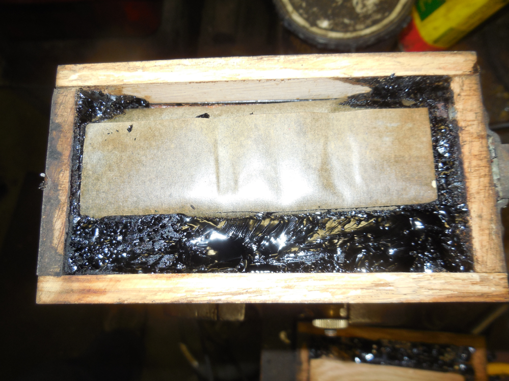
With the glued on cover off the condenser is present. It resembles a bolt of cloth and is wrapped in paper.

The wax insulated condenser exposed and ready to extract.
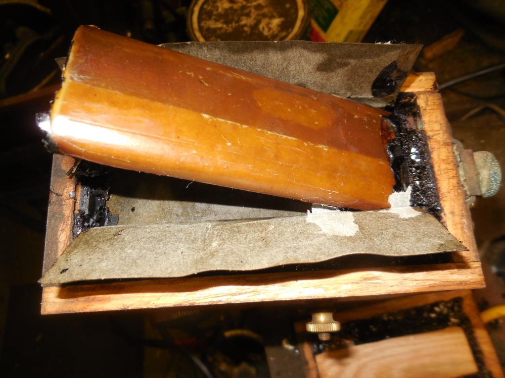
Yip the devuce upward and snip the two leads goinf into it on top. This is where the new capacitor will connect.
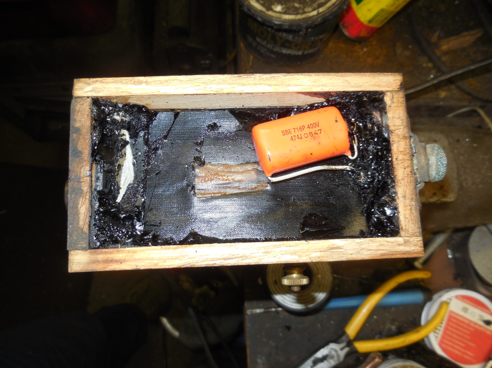
With the new capacitor in place the cover can be glued back on for the next millenia 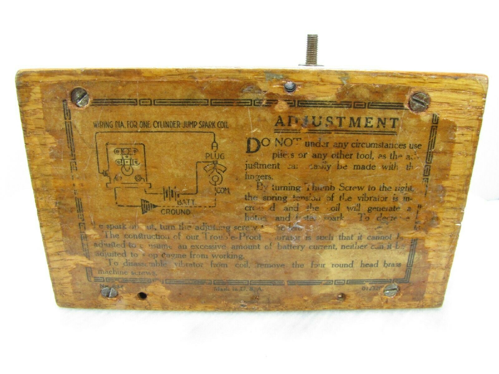
Most buzz coils on early stationary engines are connected as shown for the Jefferson model 51 coil . The tension adjustment should be just enough for it to buzz. This will save wear on the contacts and battery life.
