There are no products listed under this category.
Shop by Category
Remy Battery and Distributor Ignition
The Remy battery ignition systems probably worked well in the day, sparing us from the maintainence of a magneto with fewer moving parts and the ability to give a good hot spark even at low cranking speeds. They had some strange quirks like grounding the high tension secondary through the mounting ears of the coil separate from the primary to connect to the chassis. and two wire distributors that did not connect to ground.
If you check continuity of the high tension windings, check from the grounded base to the plug lead. It may be 2000-6000 Ohms. The problem is that sometimes the coil secondary may be continuous (in one piece start to finish) but not fire due to internal shorts, shorted adjacent turns, and/or carbon tracks. The best method is to use a coil tester. Be sure and connect the ground(mounting ears) to one side of the primary. To make this coil work as Mr Remy intended, the mounting ears must be connected to the engine block electrically somehow to give a complete high tension circuit. Some dry type coils old and modern (as compared with oil filled coils) can intermittently break down and short inside. Some may break down when they are hot and work when cold.
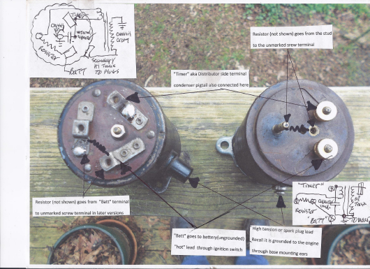
These coils are for a single wire distributor like those of later years. The coil terminal marked "Batt" should go to the battery hot lead (usually switched through the ignition switch) and the terminal marked "Timer" should go to the terminal on the side of the distributor.The lower right terminal marked "Batt" has the ignition coil primary resistor (not shown) connecting it to the coil primary via the terminal on the left.Enough to drive one "Batty!". The capacitor (condenser) inside the coil connects to this terminal and to the chassis ground. To check the condenser that is buried in the black goo connect one of the test leads to the ground (mounting ears) and the other to the terminal marked "Timer". There should be no leakage and the capacity should come in about .18-.22 MFD. These are nearly always defective and are routinely replaced. The resistor not shown goes from the "Batt" terminal to the stud or unmarked screw terminal. If you wish to check the primary windings continuity, check from the unmarked screw terminal or stud to the "Timer" terminal. It could be 1-5 ohms.

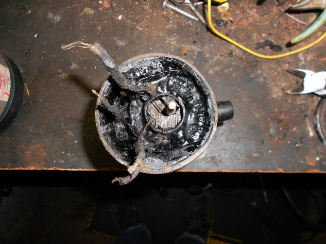
The meanest trick was to hide the condenser inside the coil covered with tar. Condensers unlike wine do not improve with age and when defective cause pitting at the points and a wimpy spark. Some mechanics in the day would gently lift the top off the coil, snip one lead off the condenser and hang the new condenser on the side of the distributor with the case connected to the chassis ground and the pigtail connected to the distributor stud. If we leave the bad condenser in the circuit with the new one it will not work well. The electrical leakage in the defective condenser is still present in the circuit. This system is OEM for our 1927 International truck.
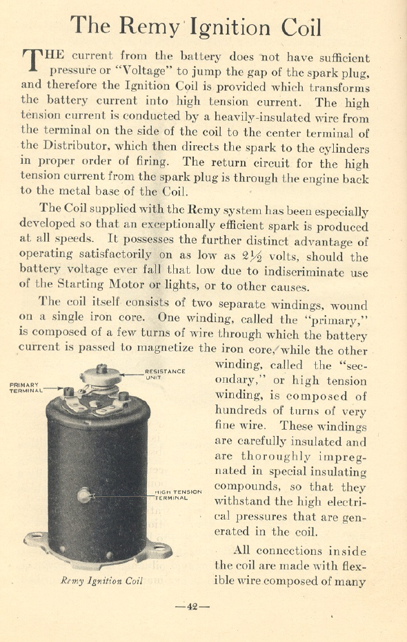
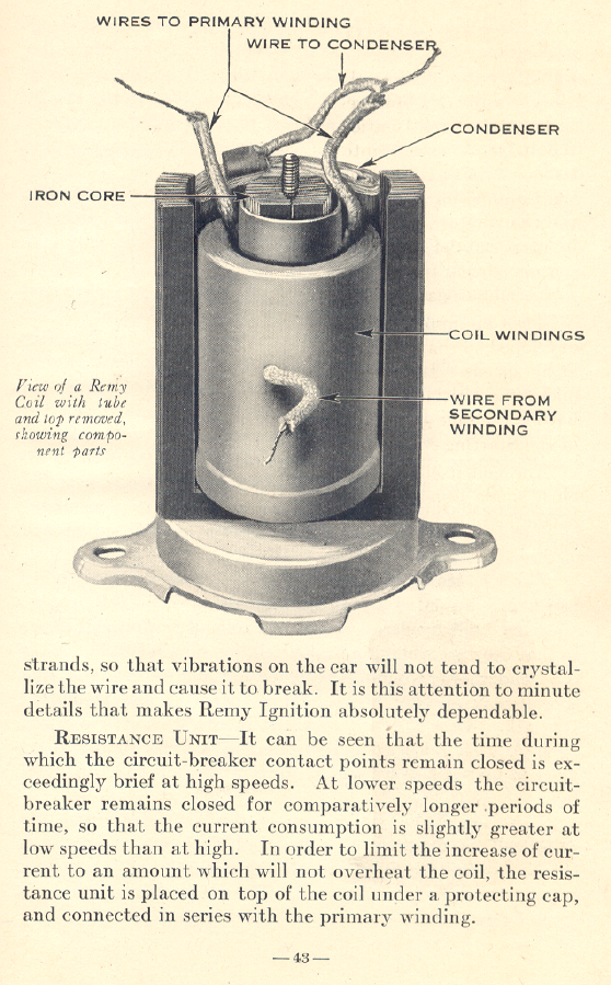
Here is some information from a Remy service manual of the day.

The other wire from the condenser and the remaining wire from the high voltage secondary not shown by Mr Remy connects to the mounting ears on the base of the coil, usually via a ring connector that goes over the long screw shown in the center of the lminated core.

If we look at the leads marked "primary" note that one connects to the "Timer" terminal and the capacitor (condenser), the other primary lead goes to the terminal marked "Batt" or battery. The other condenser lead goes to the grounded screw in the middle and makes contact with the steel mounting ears.
Some brave souls would get the coil hot in the oven to soften the tar and replace the condenser. The tar gets soft near 275-300 degrees. The best way I found to extract the condenser is to thread a wallboard screw into the center and pull it out while it is hot noting the connecting wires.One condenser lead goes to the case mounting ears (ground) usually via a ring connector held by a nut on the screw in the middle and the other condenser lead to the "Timer" terminal. The condenser looks like the end of a rectangular roll of paper, which it is. It lives just opposite the high tension post against the inner wall of the coil case. If you brave the hot goo with a wallboard screw to extract the condenser, be carefull not to damage the actual coil windings in the center of the can.The coil windings are the rounded circular feature with the iron lamination ends and a screw visible in the center. The condenser is against the wall. The condenser is between the outer wraps of the coil and the wall with the short wire protruding below the long wire . It should come out peacefully. One condenser lead goes to the terminal marked "Timer" and the other lead goes to the gounded mounting base or the screw in the center that is connected to the base. When you disconnect the condenser from the ground be careful not to also disconnect or damage the coil ground lead which shares the same ground before reassembling.

An automotive distributor condenser will work electrically if it will fit.Snip off the spade or flag terminal and solder to the "Timer" terminal, then use a nut and screw with a short wire and ring connector to connect to the grounded base or screw in middle. If not get a capacitor from an electronics supplier like Radio Shack or TubesNMore of Tempe, Az. The capacitor should have capacity of about 0.2 MFD at 400-600 volts DC. Use the 600 volt device if it will fit, use the 400 volt rating if it will not.
