There are no products listed under this category.
Shop by Category
CM4/CT4 Eisemann Magneto Instructions
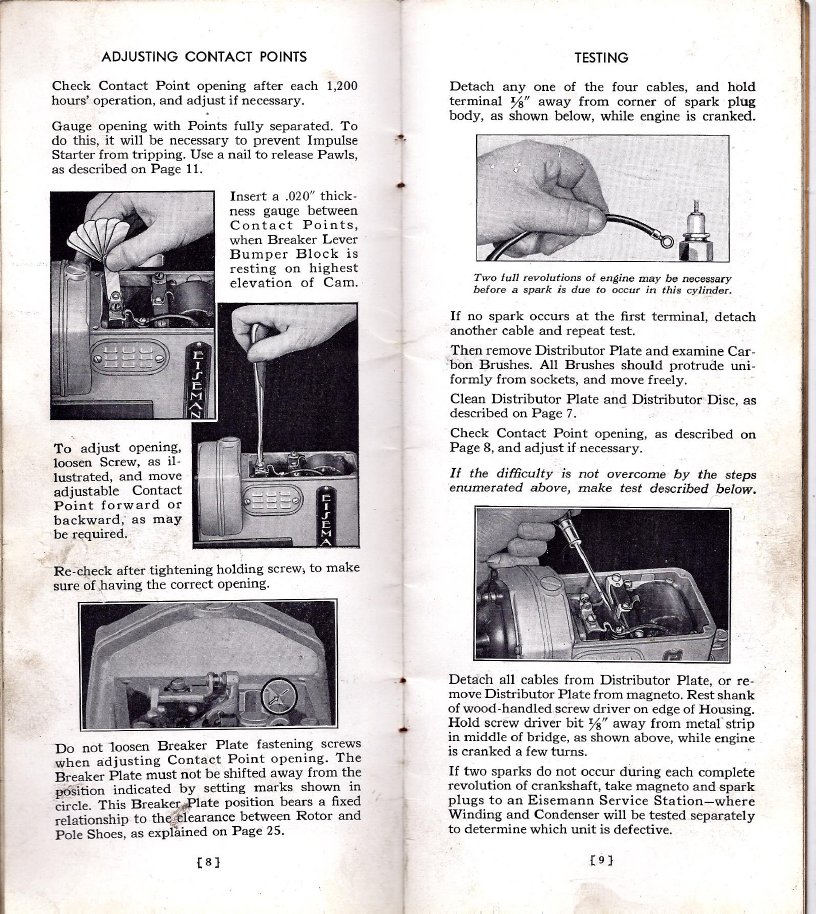
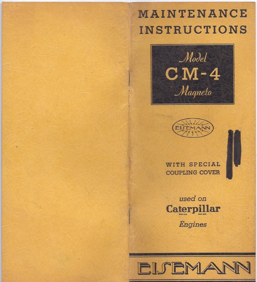
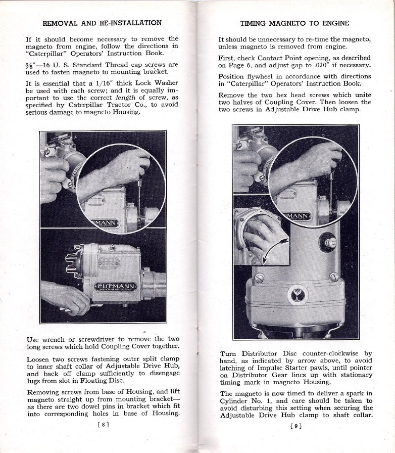
The Eisemann CM4 and its predecessor the CT4 are in my opinion are among the biggest and the baddest pieces of ignition equipment. They were standard equipment on the famous Caterpillar 22,R2,R4, and other gassers of the day. Despite decades of service and neglect, many of these cats still have their original mags. The coils were robust, wound with wire 2 sizes bigger than most. they were mechanicly very robust, the bearing supporting the distributor shaft is huge. The impulse couplers are enclosed out of the elements and the point contact surfaces are huge. They suffer from the usual, too much Oregon rain, leaky condensers,corroded points, and lack of lubrication from petrified grease. The CT4 used a stationary horseshoe magnet, the CM4 used a stronger more modern alloy rotating magnet making it even hotter. They were very similar mechanicaly.Points are set at .020". These are pages from the Caterpillar Eisemann factory maintainence brochures. Timing is set by loosening the two screws on the split splined coupler. Be sure the coupler does not crowd the micarta drive disk against the front of the magneto impulse coupler. This will cause stress on the armature bearings and sometimes will make the impulse hang up and not snap. The factory manual specifies .015" of clearance between the drive disk and the front of the impulse coupler.If the impulse hangs up and fails to engage and snap it also fails to retard the spark, instead giving a full advance. With the choke out and a rich starting mixture and no impulse to retard the spark your tractor may become an armbreaker. As always practice safe cranking and be sure the tractor is out of gear because with hot spark and a rich mixture it will likely fire up and you are standing in a very bad place! Always get the manual and read it for your tractor, for safety and more enjoyment.
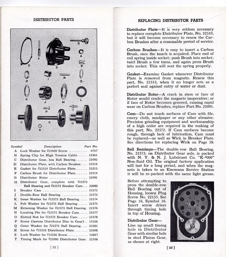
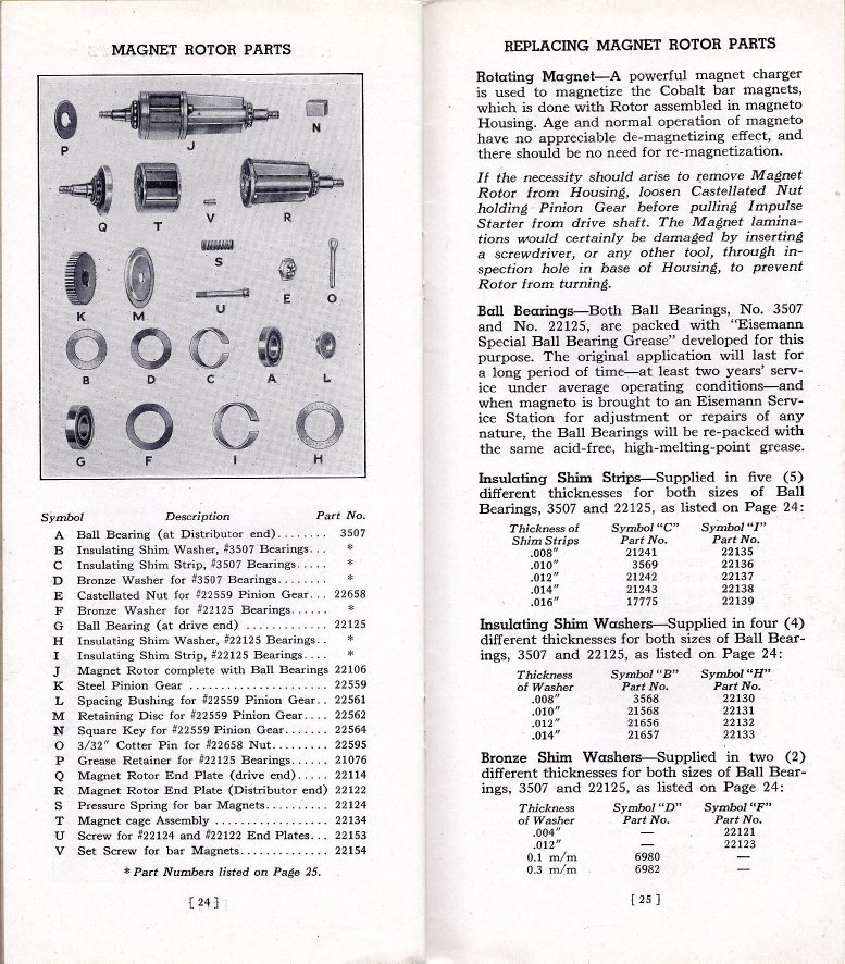
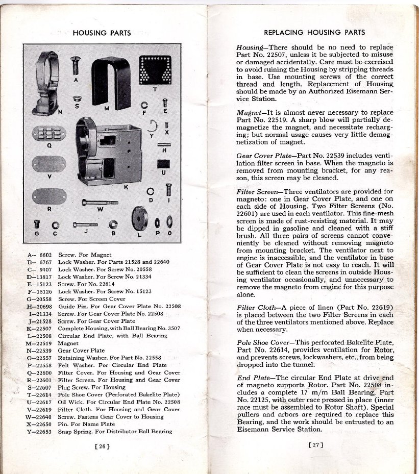
Here are some images from the owner's manual for the CT4 and CM4 to share. Note the large horseshoe magnet wrapped around the front of the CT-4. If the magnet does not come peacefully, get a piece of 1/4" x 2 barstock against the end and give it a smack with a hammer, strike equally on each side and it will come off. Be carefull as magnets can be hard and brittle. Never directly apply heat or strike a magnet. Blast, prime and paint the magnet but leave the surfaces mating with the pole shoes shiny bare metal with a thin film of grease. Get the pole shoes shiny and the magnet should slide back on easily.
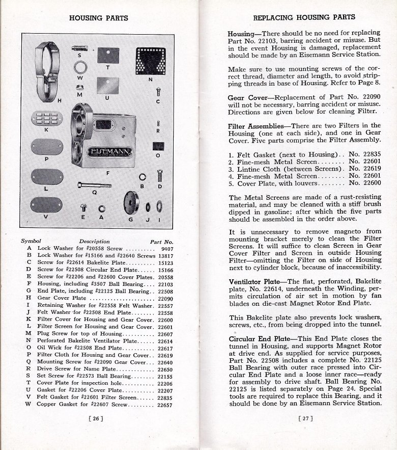
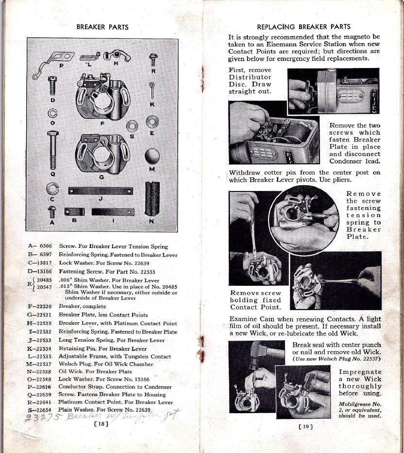
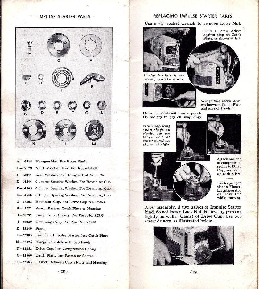
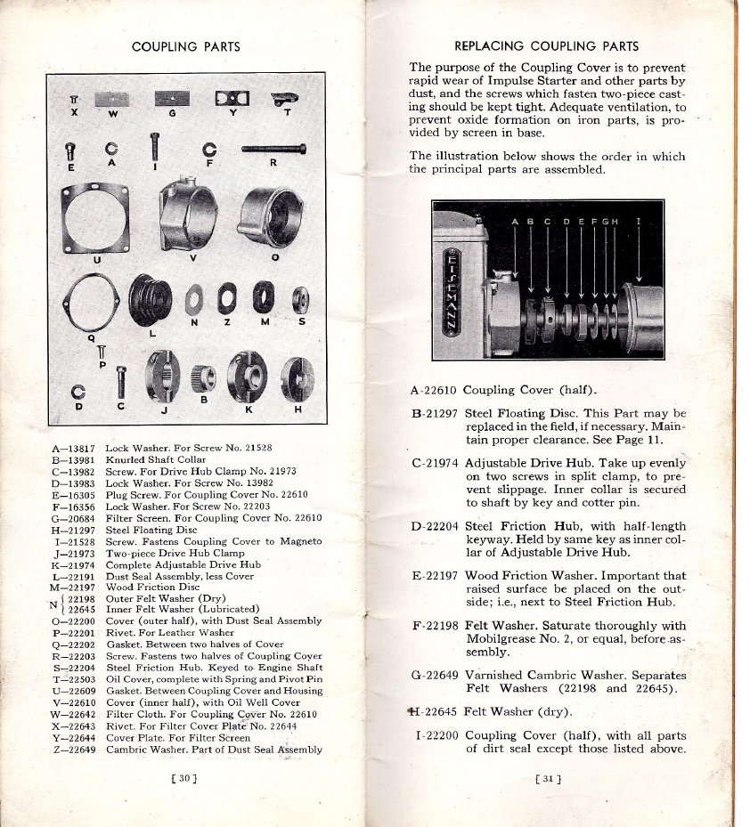
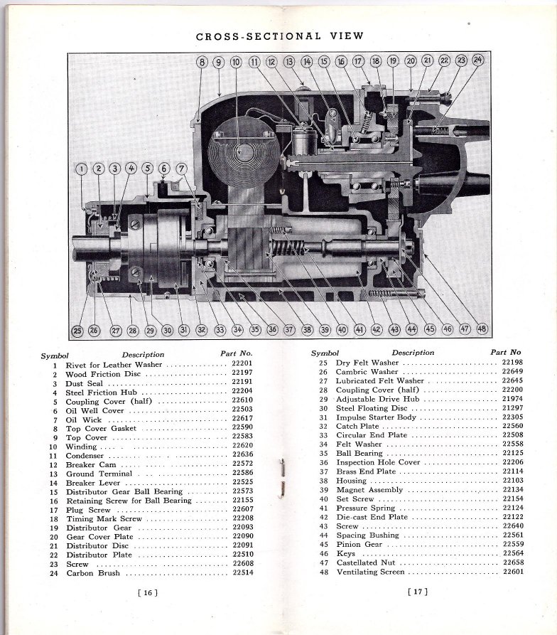
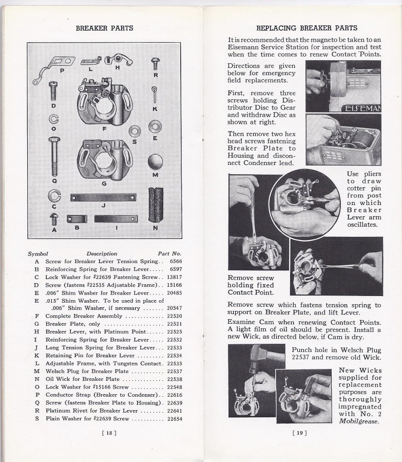
Some CM4/CT4 repair procedures to follow including that pesky special condenser made of unobtainium.
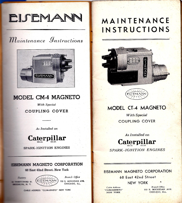
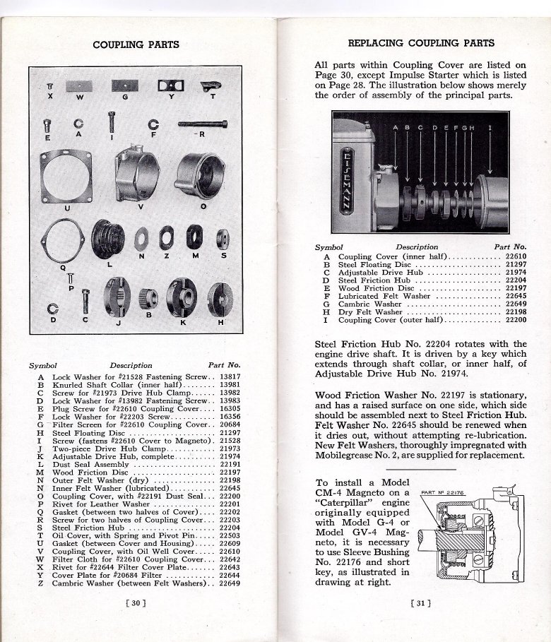
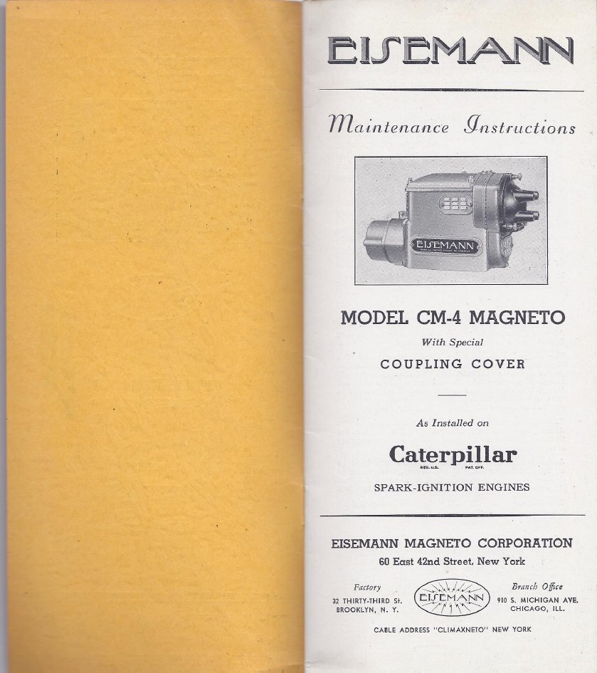
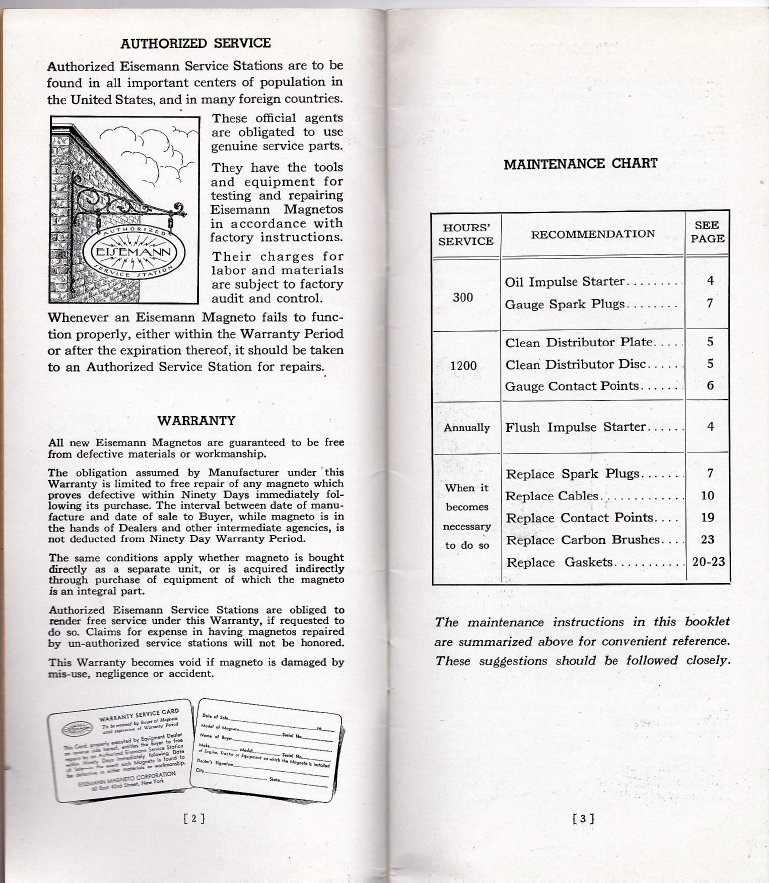
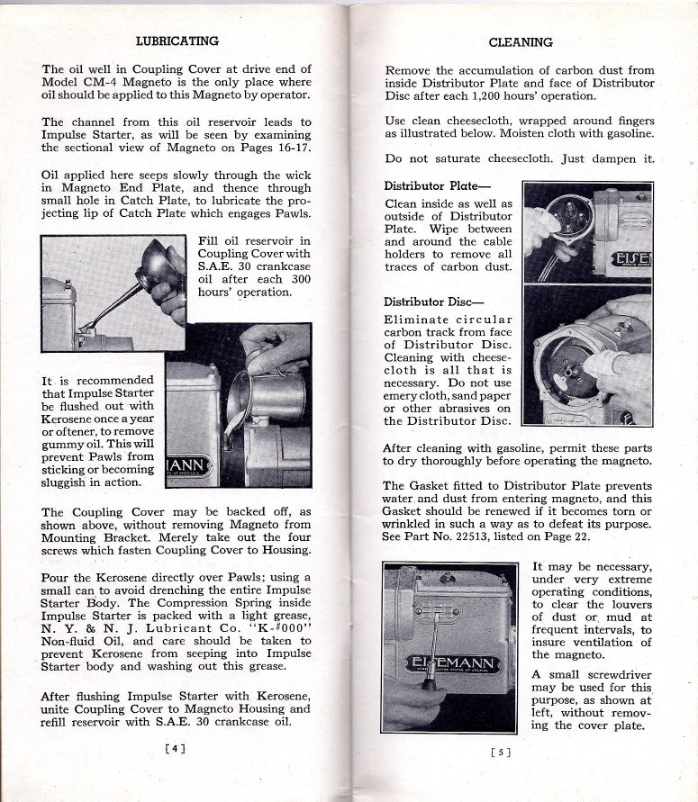
These images are from the factory owners brochure that came with the new magneto and is nearly always lost.

End view showing impulse cover that is often missing.
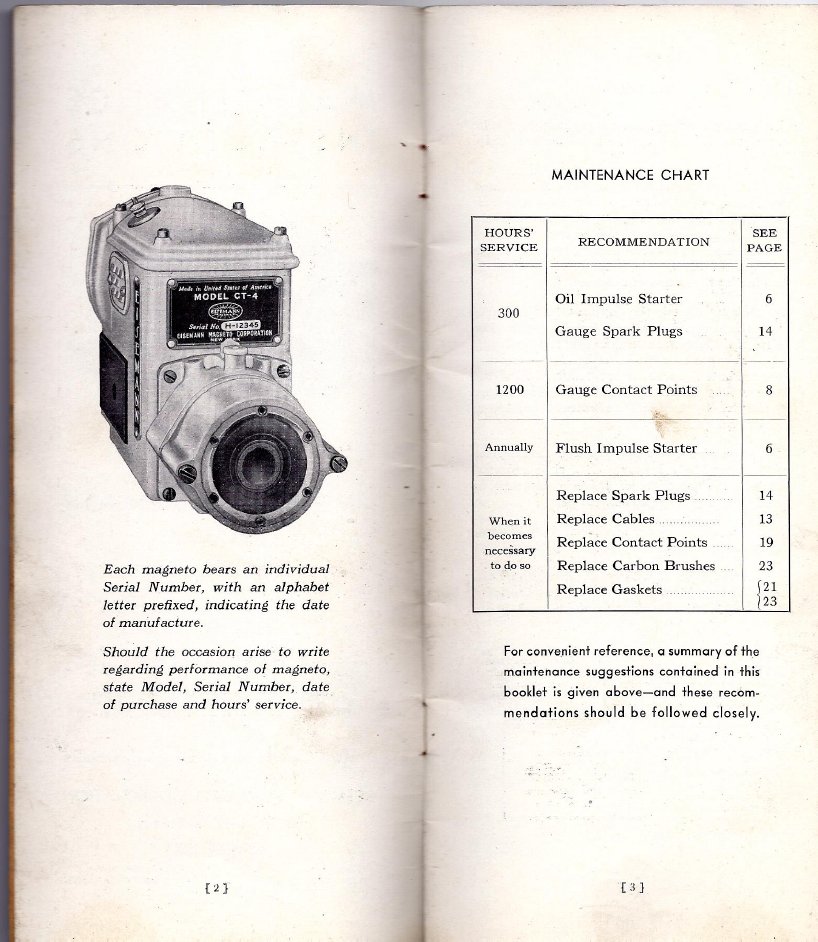
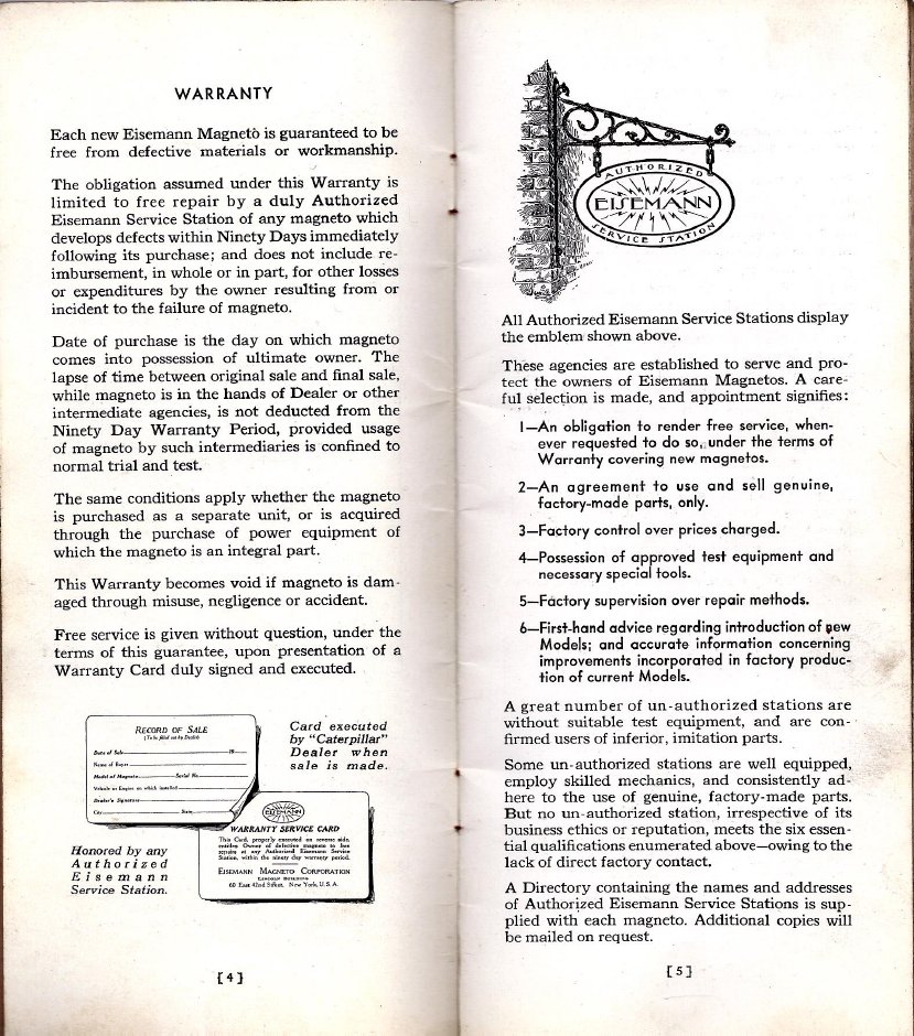
More from the factory service manual. Your mag is probably out of warranty. If you can find an Eisemann dealer, please let us know!
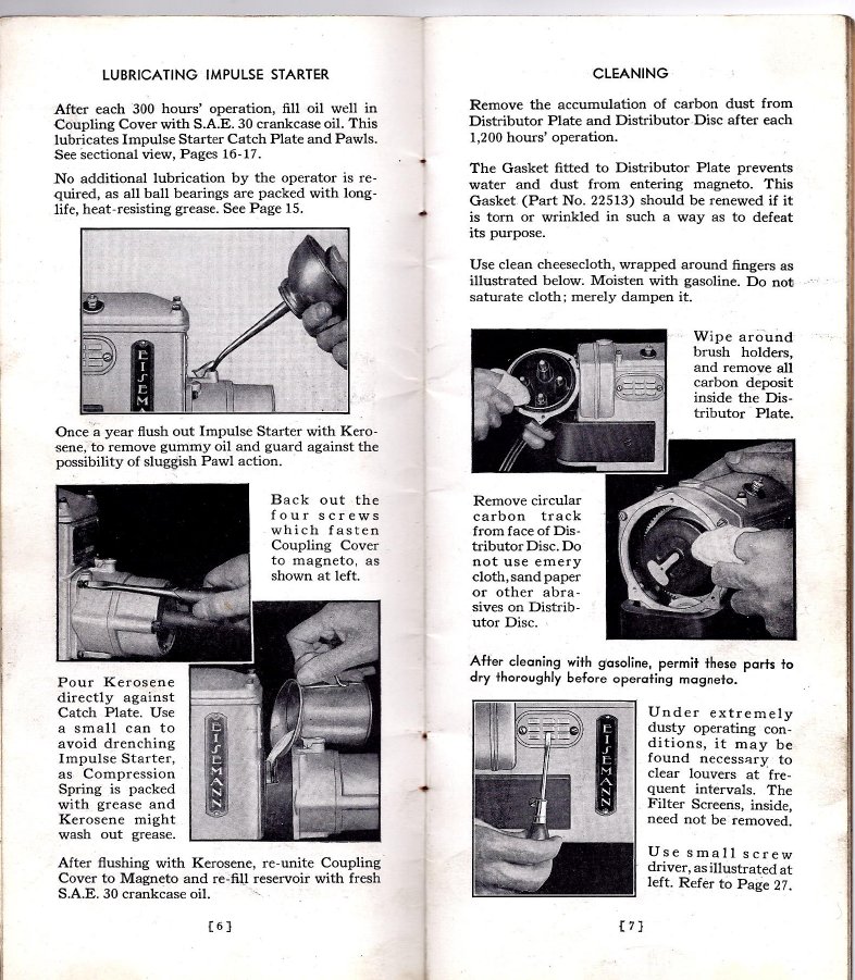
Impulse starters get no respect. Often found rusty, devoid of lubrication and full of dirt. Best to pull the impulse coupler off, disassemble, wash in solvent and relube. Pack a sparing amount of black molybdenum axle bearing grease in the spring cup, carefull not to get on the impulse pawls. Make sure they swing in and out freely. Clean the distributor plate and rotor with an electric motor cleaner or brake cleaner as shown to remove stray carbon dust from normal wear. Be sure that all is dry before reassembly and use as it can go boom with any hint of a spark and damage an expensive and scarce part.
Dirty and unadjusted points are the first place to look when there is no spark as shown in the Eisemann manual. Never use a points file, much
too coarse and removes too much material. Use a fine stone or Cratex abrasive stick(looks like an eraser with abrasive in it). Points that are smooth
stay cleaner longer. If they are very jagged, sometimes a diamond lap (like an Easy Lap) will giterdone, then follow with a stone or cratex for a
smooth finish.
If contact surfaces are very rough, always check the condenser. They were well made but do not improve with age. First test for leakage,
then capacity. It should come in around 0.2mfd.If the device is leaky, replace it.A leaky condenser will give overstated capacity readings.
If the condenser is defective you can replace with a capacitor rated at 0.2MFD at about 400
volts. we use an SBE device(commonly referred to as an "Orange Drop") available at antique radio and electronic retailers. They are made to
handle spike currents with polypropylene film as an insulator inside. TubesNMore of Tempe, Arizona has these. They are made by SBE/Vishay and are part #716P224J.
You can take the innards out of the old condenser and poke the new capacitor partly inside the can taking care that there is proper
insulation on the lead going to the coil primary and points. You can also remove the innards from the old condenser and hang an automotive
condenser inside with one lead (usually the housing) grounded and the pigtail connected to the screw terminal where the points and coil
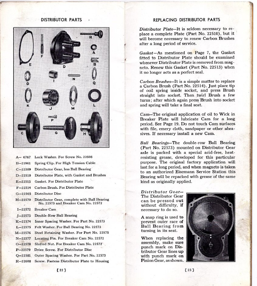
connect.looks tacky, but will get you going until proper repairs can be made. Always remove a defective condenser or the innards when installing a new one. The old condenser housing is needed to anchor the jumper from the
points and the coil lead as well as make contact with the stop switch connection in the lid.
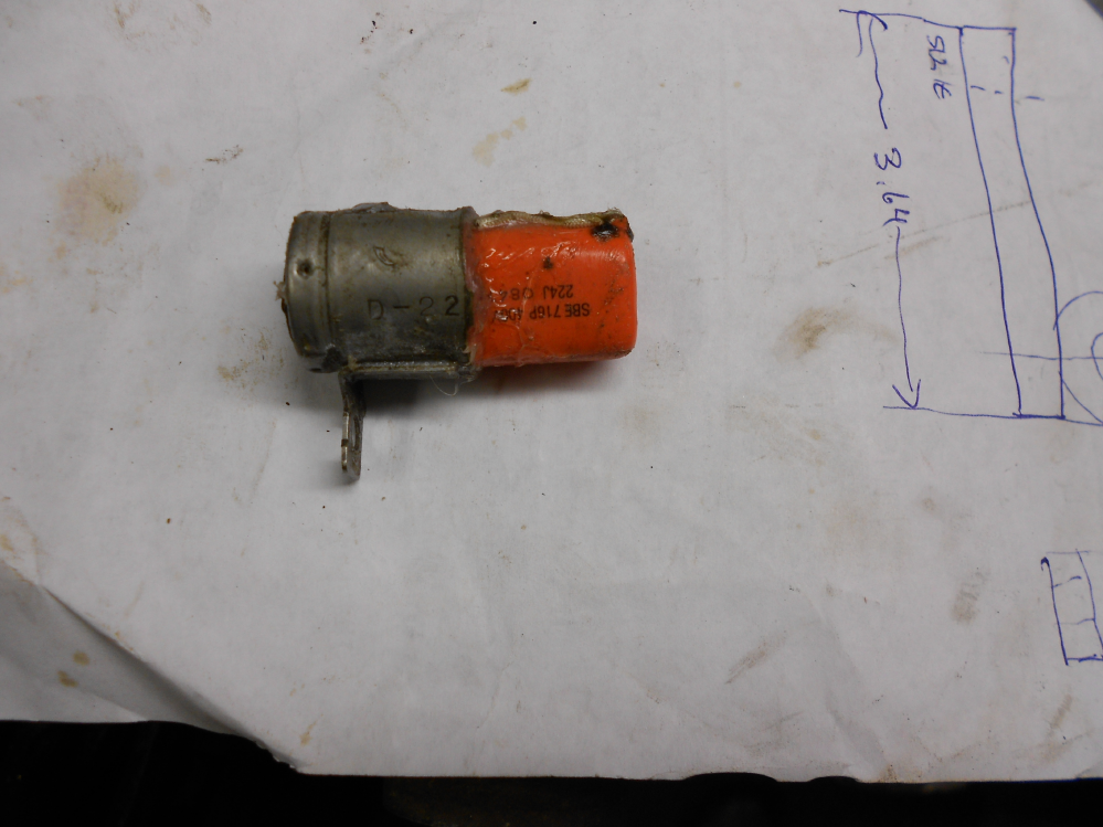
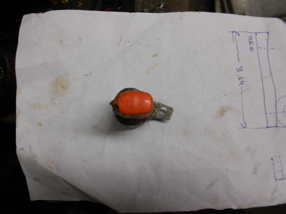
Use insulating sleeving on the capacitor leads, solder one lead to the case, The other lead is to be connected to the center brass stud inside the can. You can remove the nut inside the can, attach a short insulated pigtail soldered to a ring connector to the stud and replace the nut and splice the pigtail to the ungrounded capacitor lead. When all is connected, test the assembly and if all is well tuck the pigtail up into the can as far as it will go and secure inside with RTV silicone.
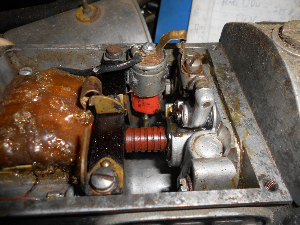
Here is one such installation in our trusty Cat 22. Note the view of the end of the new capacitor. It barely clears the rib of the housing. The epoxy hermetically sealed orange drop capacitor with polypropylene as an insulator in lieu of paper should be nearly immortal.
I hope there are no cracks or moisture in the plugwire insulation on the right or Mr Hands is going to get a good dose of shock therapy. Testing for spark with the wire connector 1/8" away from ground will more accurately determine if there is enough output to fire the plug under compression with a fuel/air mixture. Be carefull when adjusting the point clearance, the clamp screw is threaded into a micarta block and easy to strip out.
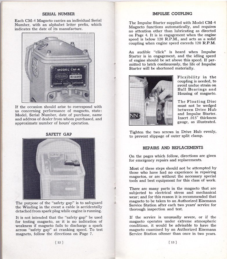
Timing is important for easy starting so your tractor does not become an armbreaker. Note the image from the Eisemann manual on the right with
the feeler gauge checking clearance between the adjustable drive collar and the float disk. If the adjustable drive collar crowds against the float (Micarta Disk)
it stresses the impulse and causes it not to snap and retard the spark when starting. The tractor manual describes timing marks on the crankshaft
pulley that are usually rusted away or covered with grease, dirt or paint and lining up a mark on the distributor rotor under the brass plug when the points open.
The other way the rest of us use to get in time is to adjust the coupler so the impulse snaps at top dead center. We do not recomend a timing light. If for some reason
the magneto does not have the required 35 degree lag but much less, the light will get you in time while running but may create an armbreaker
at(hand) cranking speeds.This can be a big problem with a replacement mag. Many later mags have less than the required lag angle.
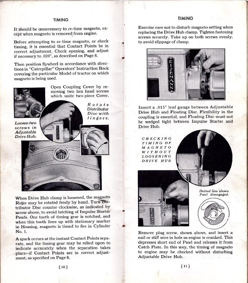
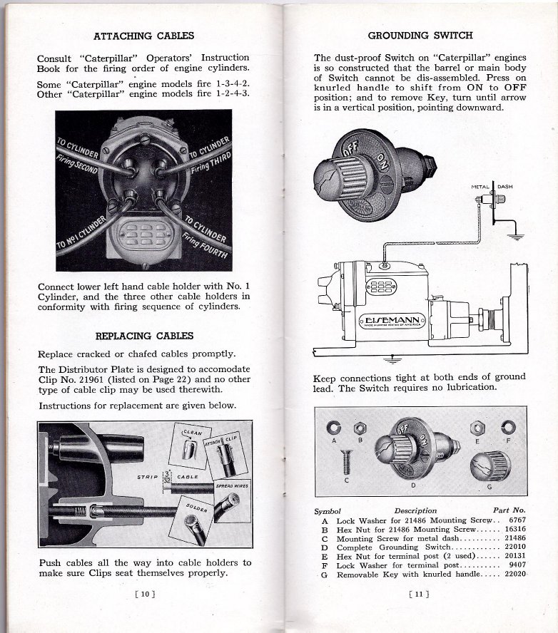
More wisdom from Mr. Eisemann on page 13: We always solder the ends of the plug wire terminals. It makes a positive connection and keeps the end
from coming off when the wire is removed from the distributor cap. Firing order does vary on some tractors. It should be in the owners manual.
The distributor rotor turns clockwise when facing the distributor cap. Position on the cap is not critical so long as the wires are placed in the proper
firing order for the tractor. Whoever wrote the brochure for timing the model 22 must have had very skinny fingers to get #1 on top dead center, the
spark plug hole is right behind the crankcase breather. We rather time it on #2 as a reference and follow the firing order 1342, and of course the
clamp screws on the adjustable drive coupler should be pointing up so they can be tightened with the needed .015" of clearance between the
adjustable clamp and the Micarta disk.
If the impulse wants to wind up and bark the skin off your finger before you get to the proper position,
you can turn the mag backwards till it lines up or you can remove the short vertically mounted 10-32 fillister head screw over the impulse cover
and poke a rod or small screwdriver in the hole to disengage the impulse when you get close to the proper position and the impulse pawls start to engage
and wind up the spring as shown above on page 11.
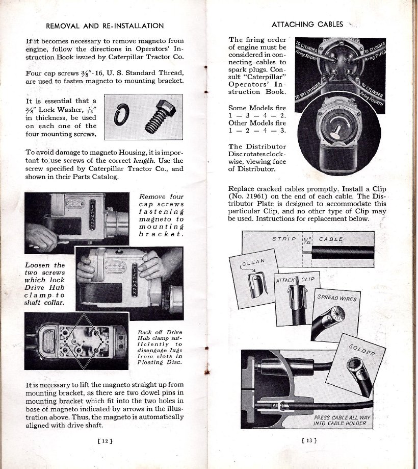
Do not forget the grounding switch accessible from the operator's seat for safety's sake. Any switch will work that will connect to ground. This makes
good sense and is required at many events. If the tractor has electric start, be certain that the magneto stop terminal never gets power connected
it. This will destroy the points, coil and discharge the magnet.
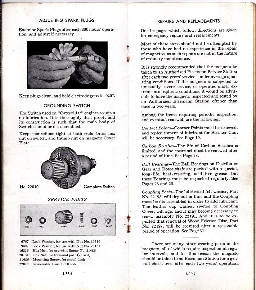
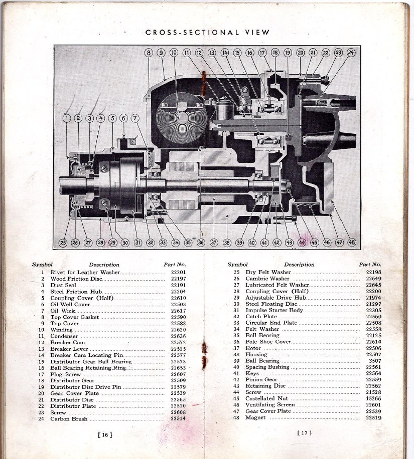
Be careful of the point spring screw,(See page 19) it likes to fly through the air and is a metric thread. Also be carefull not to over tighten the stationary point clamp
screw, it is threaded into a micarta block and easy to strip.
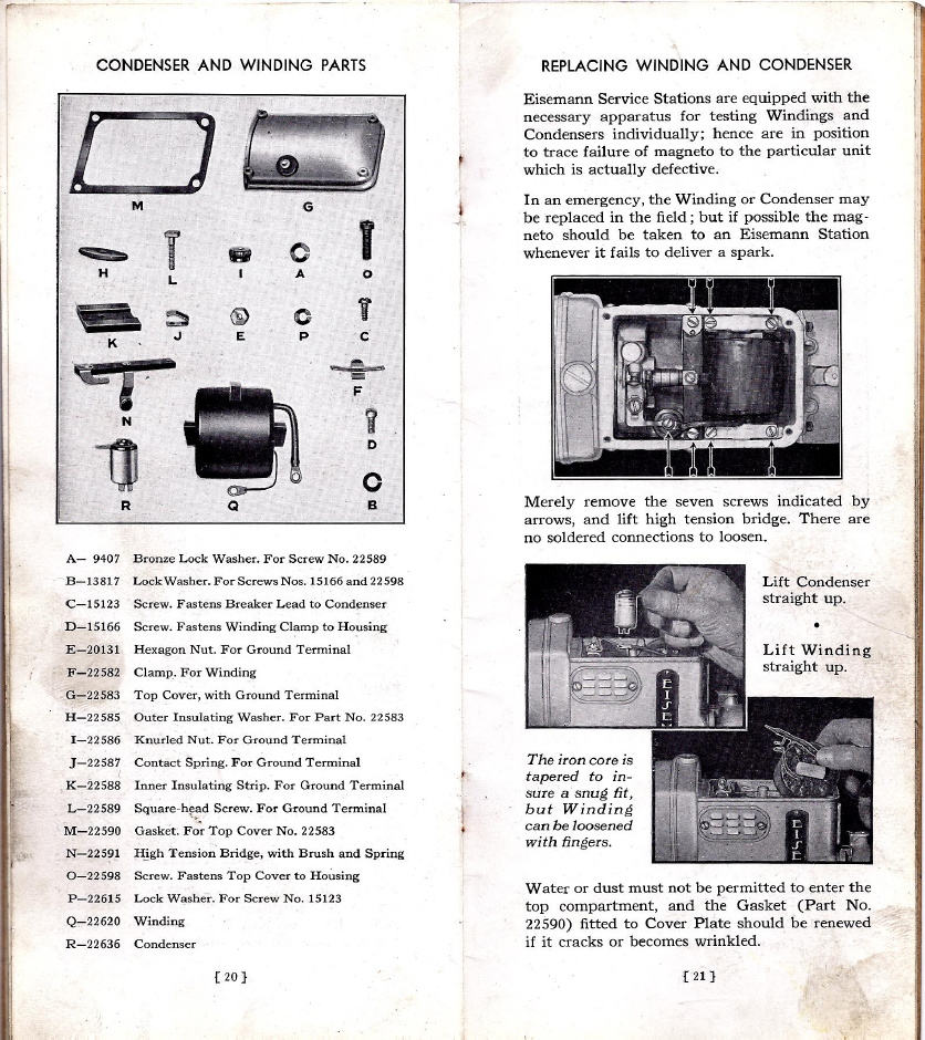
Always check the condenser for electrical leakage first with an actual automotive condenser tester. If there is leakage, it needs replacing and will show an overstated capacity value. A defective condenser will cause potting at the points and a wimpy spark or no spark at all. If no electrical leakage present, then check capacitance. it should come in around 0.2MFD thereabouts. Once in a great while an open device will be found showing no capacity. Windings occasionally fail. Continuity is not a reliable test. Best to test with a magneto coil tester like Eisemann supplied or a Mercotronic or Graham Lee that actually pulses the coil and induces spark voltage.
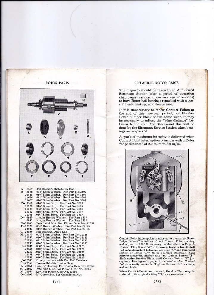
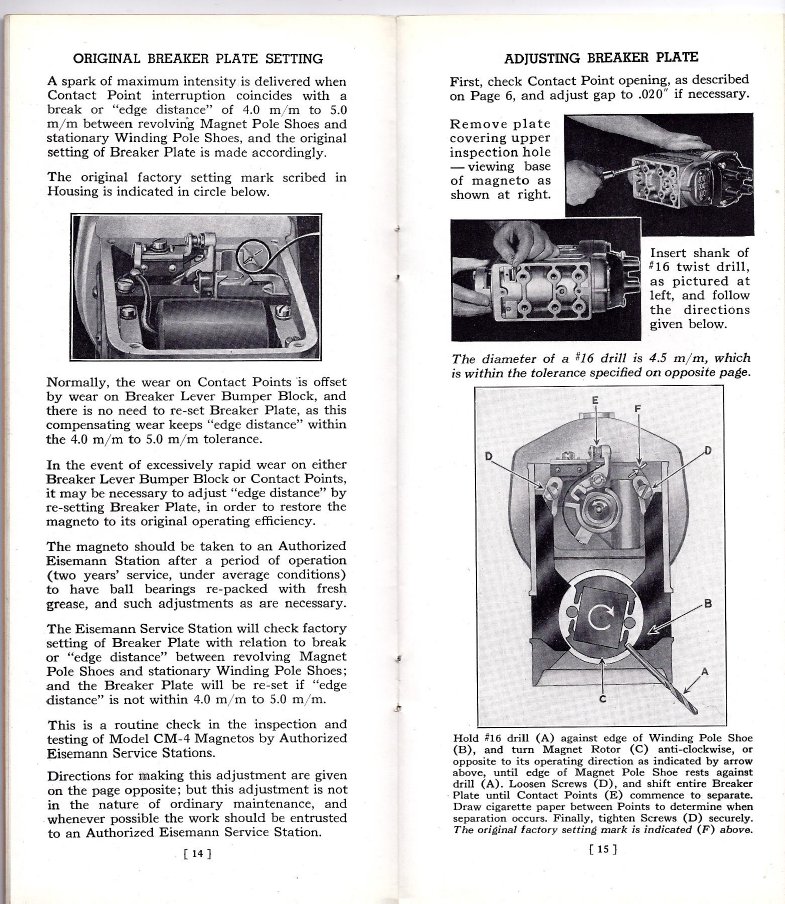
Now you know what that brass plug on the side of the housing is for. That is how you set and check the edge gap to properly adjust the breaker plate so it opens the points at the optimal time. The goal is to time breaking the electrical circuit with breaking the magnetic circuit for optimal output. If this brass plug does not come quietly, or the one on the top of the rotor housing, use a large screwdriver bit in an impact driver and give it a good smack and it will let go. When in doubt about edge gap, line up the witness mark on the breaker plate with the mark on the housing and usually all is well.
The best way to pull the impulse coupler is with a small bar puller.The picture shows a good way to ruin two screwdrivers. This was probably not a good idea. There is a holding taper and a woodruff key that can hold the coupler with a vengeance. If it does not come quietly with heavy pressure from the bar puller, give the pressure screw a smack with a brass hammer and it should let go. Loosen the 3/8 nut holding the coupler on, but leave it partly threaded on the shaft so when the coupler hub does let go it won't go flying. If you don't really need to remove the pawls, best not to do so. Those C- ring retainers are hard to get on and off.
If the tractor does not stay in time, always make sure that the adjustable coupler clamp screws are tight and leave .015" of clearance between the
adjsutable coupler and the floating disc. Recall if the floating disc is crowded against the impulse hub it may not properly engage and snap.

Here are the images from the Eisemann factory brochure for the updated version of the CT4, the CM4.These are very robust designs and perform
well even when all things mechanical and electrical are not well.
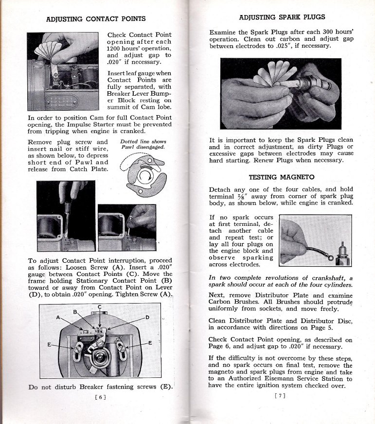
Testing the magneto to first see if it is a magneto issue at all is a logical step one. Fouled plugs and some modern fuels will sometimes act like no spark is present despite a hot mag.
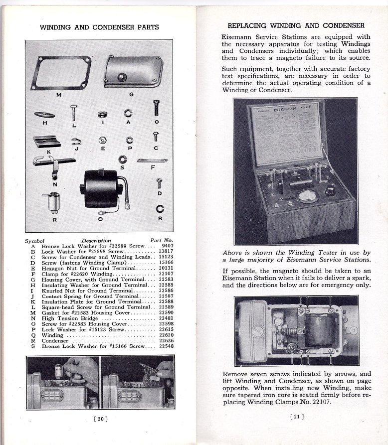
Eisemann made an excellent winding tester. The one shown plugs into a wall socket and uses a 6 volt battery. A later diecast version was offered. These are excellent coil testers.
