There are no products listed under this category.
Shop by Category
International Harvester H1 H4 Magneto RX
International Harvester introduced the H series somewhere in the late 1930's as an updated version of the familiar F series. The H series featured a more compact design and a more modern rotating magnet and a jump spark distributor. These are excellent hot magnetos. They shared some of the parts with the F series like the condenser and coil, both readily available. They seem to fire even when all is not well. The International LA and LB stationary engines used this model with a gear driven impulse making this engine extremely reliable. The diesel tractors and power units used a slightly different flange mount and operated counterclockwise. The most common will be the clockwise rotating flange mount used on the letter series tractors.
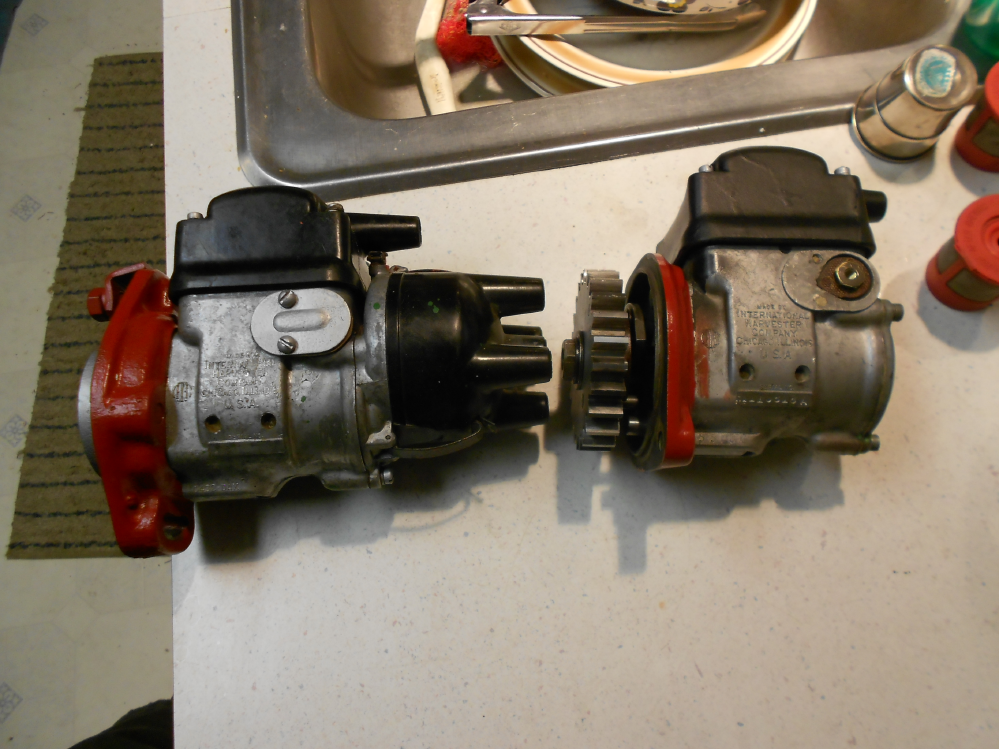
Corroded points are the most common cause of trouble as a rule. Get the rough blemishes off with a stone or fine diamond file then polish to a mirror finish and they will stay clean longer, with care not to damage the bakelite block when removing and replacing.Add a small dab of grease to the brass pivot pin when reassembling. The H1 and H4 used the same points. Set them so the contact surfaces line up when closed with .013" clearance when open and add a small dab of grease to the cam.
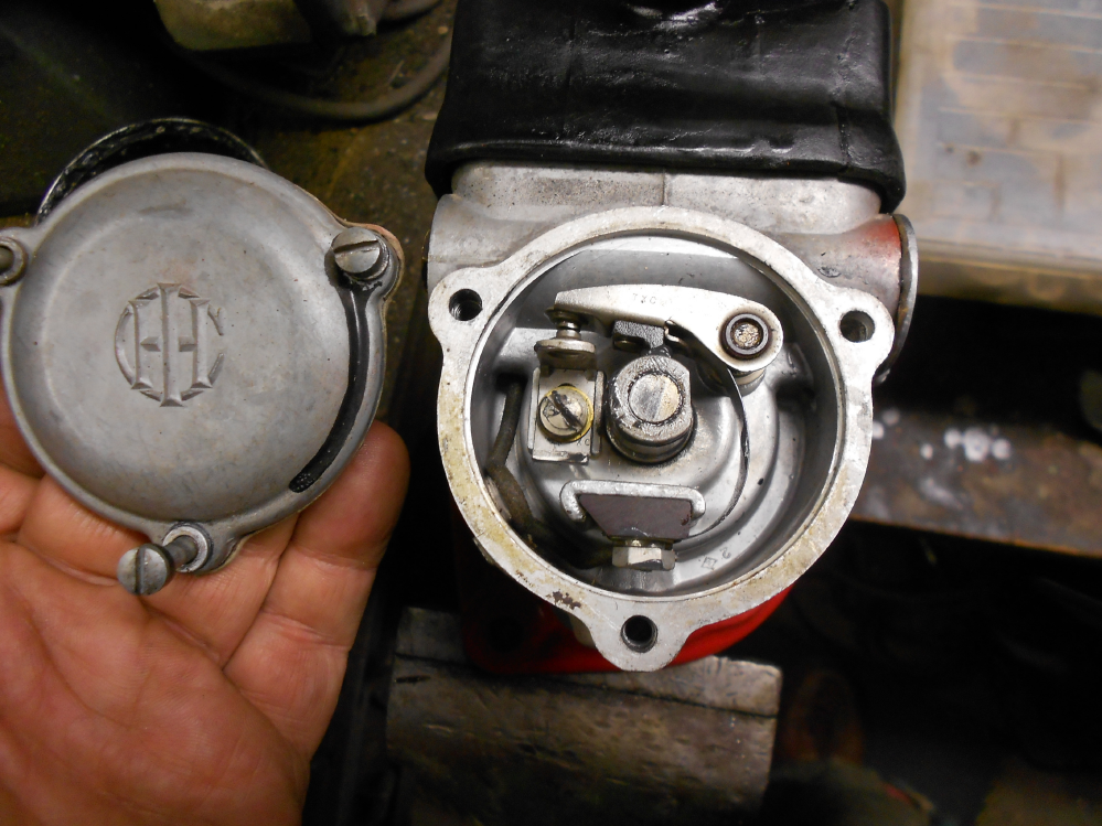
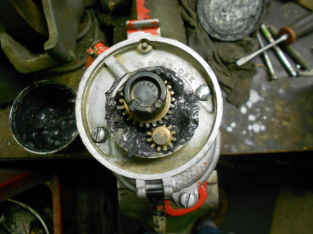
While we are here it is helpfull to wash out and relube the timing gear case if it is an H4. According to literature, modern lube under ideal conditions may last up to 30 years. Most examples found are far past the "Sell By" date and petrified. It is important to mind the witness marks when reassembling. If you look at the end of the rotor shaft, there are two notches, one marked R and the other L corresponding to right or left hand rotation. Recall some diesel tractors and power units use a left handed rotation, the rest are right hand rotation. If the mag is right hand rotation as used on the letter series tractors, line up the gear tooth below the notch marked R with the beveled or otherwise marked tooth on the smaller steel gear as shown. If the points still have meat left, by all means use them. Use a fine stone or diamond file to remove any jagged edges and polish to a mirror finish with a Cratex abrasive stick. The Cratex stick looks like an eraser and has abrasive in it. The red is a medium grit and the slate is a fine grit. These work great in the field. Smooth point contact surfaces will stay clean longer than rough ones.
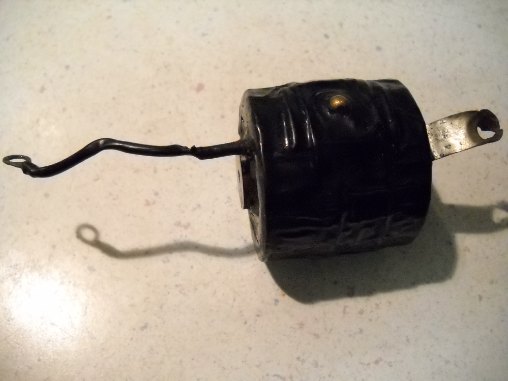
Problem areas for these are the usual ravages of moisture, wear and petrified lube. If the tractor lived west of the Cascades it probably got a heaping helping of moisture and and can often be found with a bad condenser. always test for leakage first, then check capacity. If there is leakage, it will read erroneously high capacitance. If it is leaky, best replace it. A leaky condenser (capacitor for engineering majors) will cause pitting at the points and a weak spark. Capacitance should come in near 0.2MFD or so. Most testers of the day show an acceptable amount of leakage, but I typically replace with any signs of leakage and keep the old capacitor in the toolbox for a spare.
The coil is held in by two #8 flat headed machine screws on each side of the pole shoes. Remove the screws and gently pry the coil assembly up. The coil has a machined laminated core that fits precisely between the poleshoes. Always test the coil with the core in place. If the coil is defective, save the core as it is not integral with the coil. Care must be taken not to mar the core ends. The precise fit of the core and pole shoes allows maximum transfere of magnetism through the core.
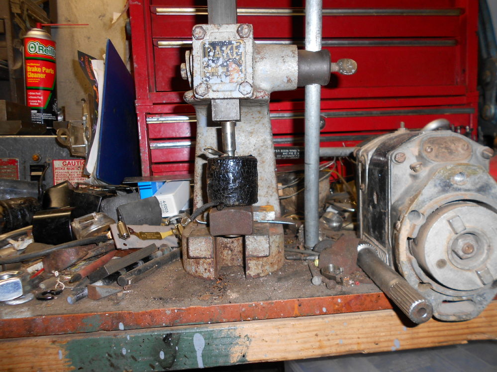
The best way to prompt the core out of the coil is to put it in the oven (toaster oven works great) and get it hot to about 250-300 degrees. When it is good and hot the goo holding the core in place will let go. Never hammer the end of the core, rather give it a push in an arbor press while supporting the coil. A piece of steel or wood with a hole in it to accept the core while pushing works great. Here we are using a large nut and a piece of shafting to push it out. The workbench looks like it suffered a direct hit. If the new coil does not slide over the core easily, carefully run an expansion reamer through it or carefully use a rat tail file to smooth off any burrs or flashing inside and smear some grease on the core and poleshoes when reassembling.
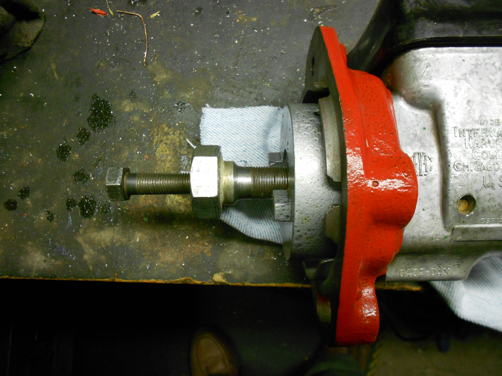
Getting inside this one goes a bit differently. To remove the hub, first remove the 3/8-16 hex nut and washers, then a special puller is needed to thread into the center of the hub. The internal threads are 9/16-24. This tool can be made from a large Grade 8 bolt with the unthreaded shank turned and threaded with 9/16-24 threads and internally threaded with 3/8-24 threads to accept a grade 8 bolt as a pressure screw or this tool can be purchased from magneto parts suppliers. The hub is hard and brittle and may break if it is grabbed from the outside and pulled with a leg puller. Don't ask me why I know that. Thread the puller into the hub as far as it will go, then thread in the pressure screw in the center and it should come apart. From here, remove the Woodruff key and slide the front flange off, then wash and repack the bearings with a good molybdenum grease. Be carefull to keep any metal chips or filings away from the magnetic rotor. Polish the breaker cam with crocus cloth and a flat straight edge if tarnished. Give the inside of the housing a bath to remove any foreign debris. If the bearings are rusty, they should be replaced. They are E15 type and are readily available and reasonable from many motorcycle parts dealers, especially in the UK. If you replace the bearings, a seal kit should be purchased and installed at the time. The E15 is a thrust ball bearing that can be a bugger to remove and replace without proper pullers. It is also important when replacing the bearings to allow some endplay (about .001-.002") to prevent damage to the bearings. Endplay is adjusted with special metric shims behind the inner races on the shaft.
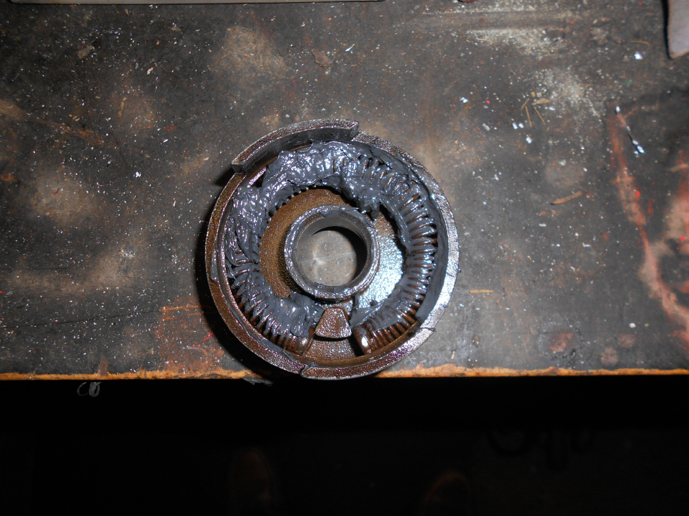
The impulse cup and spring should be removed and washed of dirt and debris. Replace it if broken or distorted, then reinstall with a good smearing of grease carefull not to get any on the pawls that must swing freely to engage the impulse coupler.
Replacement parts for the H1 and H4 are readily available for these. The coil is part #361 114R1 or NAPA#IH1851. The condenser is part#373892R1, or 71455C1 or NAPA#IH201. The breaker points are part#353171R91 or NAPA CS1601.
For the H4: The rotor is NAPA part#IH301. The distributor cap is part#47413DX or NAPA part#IH351. The coil cover is#47449DAY. Farmallparts.com has these.
The breaker gap os .013", spark plug gap os .025". For H4 equipped tractors, use an Autolite 3116 non resistor plug. Use the Autolite #386 only with a batery, coil and distributor as these are resistor plugs per Autolite tech services.
For the H1 equipped engines use an Autolite 3076 or the hotter 3077 plug.
If the pawls show signs of rubbing against the housing, order a pawl kit and replace them.
The F4 and F6 use the same coil and condenser but different points. More on those critters later. They are an earlier mag but extremely hot and reliable.
