There are no products listed under this category.
Shop by Category
Testing 101
Here we will share some basic testing and troubleshooting gleaned over many years and beers from college professors, farmers,mechanics,coworkers and the college of hard knocks. We will start with some basic tests one can do without special service equipment and show how things can get really complicated, confusing and totally out of control later with test instruments.
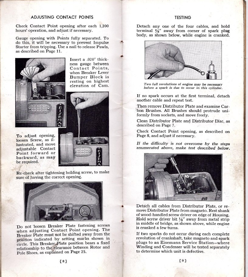
The first test to perform with a no go before a frontal assault on the magneto is to determine if it is indeed the problem. Most manufacturers describe cranking the engine at normal cranking speed and holding the end of the plug wire 1/16"-1/8" or so from the engine block and see if we have a spark. This is fairly reliable and easy to do in the field without special instruments. Presence of spark at the spark plug in open air is not a valid test as it does not accurately emulate the effects of the fuel/air mixture and compression. Air is normally an insulator but if we clobber it with high enough voltage it will break down as an insulator, ionize and conduct electricity. It takes more spark voltage to jump the usual .025" gap under compression with a fuel and air mixture because it is a better insulator than atmospheric air and therefore requires more spark voltage for it to break down, ionize, conduct electricity and make the mixture go boom.
I hope there are no cracks in that plug wire or Mr. hand is going to get a dose of shock therapy.

Be sure to check the wires and connections also. The conductors can pull apart inside the wire insulation jacket in some cases we have seen. Beware of resistor or non metallic wires, they are a big NONO with early magneto ignition systems as are resistor plugs. If there is spark but no go it could be a fouled plug. A fouled plug can short out the spark and not look dirty. Weak spark issues like missing under load or at high speed are a bit more complicated and will be addressed later.
Get to the point(s)!
Once it is determined that the magneto has low or no output, the next step is the most likely cause pf failure and that is dirty points. Point contacts can fail by accumulation of metal oxides that are hard and do not conduct electricity. Normal wear, moisture and a faulty condenser can cause this.

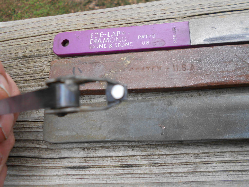
The best RX is to get the contact surfaces smooth and shiny. Smooth contact surfaces will stay clean longer than rough. Old literature describes using a wet sharpening stone to get the rough spots and polish to a mirror finish with 600 grit or crocus cloth. Everyone seems have a points file, but they are too coarse, remove too much material, and leave a rough surface. With extreme pitting a fine diamond file like an EZ Lap works well, then follow with a Cratex abrasive block. The Cratex abrasive block is one of the best contact tools we have found. Sometimes a few strokes will polish the points to like new. Start with the red (medium grit) and finish with a fine. More on this later.
If the points are clean and it is still a no go the next step is to check the condenser(capacitor for the electrical engineering types). The condenser is a device that stores electricity. In ignition systems it minimizes sparking at the contact points and intensifies the spark. The most common failure is electrical leakage or a short which is like the condenser leads are connected together inside the device . Occasionally a condenser can fail as an open where it is as if there is no condenser present at all.
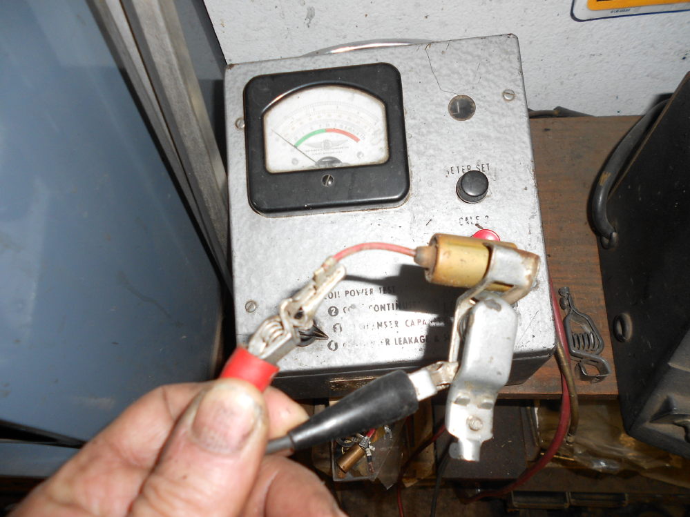
The best test procedure is to use an automotive condenser tester. Nearly all such testers work by applying a voltage of about 150-250 volts to charge the condenser and measuring the current through the device once fully charged. A good condenser will show a brief inrush of current till the device is fully charged then drop to zero. A shorted device will show heavy current and peg the meter. A leaky device will show an inrush of current but will never drop to zero. Digital multimeters are of limited use as most do not test for leakage with the spike voltages encountered when installed. They can be used to measure capacitance of a condenser with no leakage. Old service literature describes a minimum of 2 megohms of leakage at the operating temperature of the condenser and 20 megohms at room temperature. The green scale on the left denoting an acceptable device os probably reading from 2 megohms to approaching infinity. Digital meters will be accurate with a capacitor(condenser) for measuring capacitance with no leakage and will show an overstated capacitance value with a leaky device. The best scenario is with no leakage at all.

Here is a vintage Wico (Mercotronic model 60) tester. In the leakage test mode we press the red button and it hits the device with about 200 volts. The needle deflects to the right of the scale briefly then comes to rest in the green portion of the left side of the scale approaching zero leakage once fully charged. This is a good condenser. A defective device will come to rest in the red portion of the scale on the right or peg to the right. Do not touch the test leads during this test or you will git bit! When the button is released the device is discharged for safety.

Once the device is tested and passes the leakage test one can measure capacity in microfarads. Condensers almost never change in value but this is a good way to tell if the device is open or intermittent by performing the test and moving the leads while watching the meter. We have had a few of these show intermittent and almost drive us looney.
Here is a brief glimpse of some ignition service equipment.

The large device on the far right is a 1947ish Allen electrical servicer. It has a 2HP variable speed DC motor and variable width spark gaps. it will drive base or flange mounted magnetos. This is helpful to detect a miss from a short or leakage as well as how hot is hot enough to perform adequately by adjusting the widths of the spark gaps. The John Deere electrical service manual describes steady firing at a 9MM gap at 1000 RPM. American Bosch uses similar specs. For tractors this is a good ballpark target. Small engines can get away with less spark output. This is what gets done first with a suspected magneto issue. Step one is to test the magneto as a system with the Allen Electrical Servicer then if faulty identify and correct the defective components. Often it is not a magneto issue at all. Fouled plugs often cause mags to be sent in for service.
I
